4 Channel Rf Remote Control Circuit Diagram Relay Channel Rf
Rf remote control circuit Remote control circuit through rf without microcontroller 10+ 4 channel remote control circuit diagram
4 Channel Rf Remote Control Circuit Diagram
4 channel remote control circuit diagram Remote channel pcb rf schematic control Rf circuit transmitter remote receiver channel control channels four wireless circuits module figure encoder ht12d ht12e car wz x01 diagrams
Remote rf channel control diagram schematic controller tx wiring receiver decoder encoder using circuit electronics projects output yamaha lab door
Remote control circuits schematicSchematic lab schematics industrial 4 channel remote control circuit diagram4 channel rf remote control circuit diagram.
Remote pcb gadgetronicx transmitter receiverReceiver circuit diagram remote control 4 channel remote control circuit diagramMaking a 4 channel rf remote ( pcb design included).

3 channel rf remote control
Rf remote control circuitEmbedded engineering : low cost rf control 4 channel relay board 3 channel rf remote control4 channel rf remote control circuit diagram pdf.
433 mhz rf 8 appliances remote control circuit – homemade circuit projectsControl rf remote channel receiver diy hobby schematics electronic tx transmitter radio schematic circuits 3v project brings Four channel rf remote controlPin on drone.

Rf remote controller channel wiring rx electronics lab
Remote control channel circuit projectsRelay channel rf control board diagram frequency radio receiver remote schematic pcb using embedded engineering repo github hex complete code 4 channel rf remote control circuit diagramRemote control rf channel ch 12v.
Rf 4 channel remote control relay module using 433 mhz rf transmitterRemote control circuit 433 rf mhz homemade transmitter ic appliances projects schematic receiver circuits which flip flop single rx button Make a remote controlled toy car circuitRf remote control transmitter and receiver circuit.

Rf bloggang
4 channel remote control4 channel remote control circuit diagram Simple rf remote control circuit without microcontroller ( no need code)Remote control transmitter circuit diagram.
Mhz transmitter reciever relayRf remote control circuit diagram 2.4 ghz 10 channel remote control switch – homemade circuit projects8 channel remote control circuit diagram.
Circuit remote control receiver rf circuits microcontroller radio without through relay using ht ic electronic 12d projects off 2011 automation
Remote ghz control channel switch circuit arduino transmitter diagram circuits homemade wireless 4ghz projects diy schematic controller radio board make8 channel rf remote control circuit diagram 4 channel rf 315mhz remote control , schematic and pcb avaitable4-ch rf remote control.
Remote car circuit control diagram toy controlled make relay circuits homemade trolley rc wiring wireless relays mhz pdf using modules .


RF 4 Channel Remote Control Relay Module using 433 Mhz RF Transmitter

4 Channel Remote Control Circuit Diagram

4 Channel Rf Remote Control Circuit Diagram

4-Channel-RF-Remote-Controller-WIRING-RX - Electronics-Lab
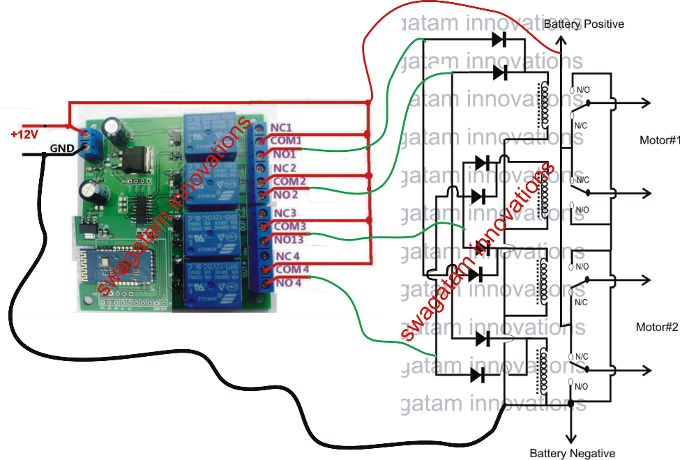
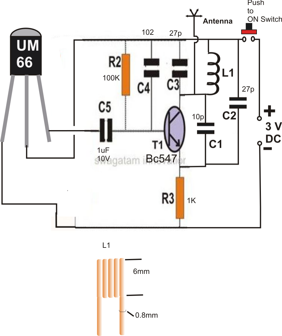
Make a Remote Controlled Toy Car Circuit

4 Channel Remote Control Circuit Diagram

Remote Control Circuit Through RF Without Microcontroller